
The RCA TT5-A Television Transmitter
WCAU-TV
1954
(Click on the photo to see a larger version)
![]()
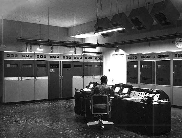
This 1954 picture shows the RCA TT5-A 5KW Television Transmitter, which became the Auxiliary Transmitter when transmitter facilities moved to Roxborough. The TT5-A and the TT50-AH were both scrapped in 1979 and 1980 when two new RCA TT50-FH transmitters were installed. Since the FH models are both full power WCAU no longer has a Main and Auxiliary Transmitter but instead a Main and an Alternate Main Transmitter.
The RCA TT5-A was brought from the WCAU transmitter site at the PSFS Building when the transmitter was moved to Roxborough in May of 1954. The TT5-A was only the auxiliary transmitter during the time Channel 10 had the TT50-AH, which was at the Roxborough location. When it was at the PSFS location, it was the main transmitter and the station had no auxiliary.
A part of the RCA TT50-AH 50KW Main TV Transmitter can also be seen on the right (four panels). The Technician at the operating console, according to Broadcast Pioneers member Charlie Higgins, is Ed Hill, Al Bizik or Ken Hahn. By the way, Charlie also said that he thinks that the TT5-A transmitter, when scrapped, was shipped to South America. A number of that model was still in use at that time by our neighbors to the south.
The RCA TT50-AH Television Transmitter & the GE WCAU-FM Transmitter
WCAU-TV and WCAU-FM
1954
(Click on the photo to see a larger version)
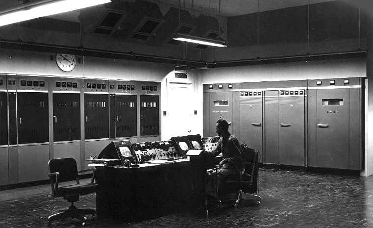
The 1954 picture shows the rest of the new RCA TT50-AH Main TV Transmitter (left) and the GE FM Transmitter of 10KW power (right), also brought from the PSFS site.
A little information about the RCA TT50-FH transmitters which were purchased by Channel 10 and installed in 1979 and 1980. The last unit of this TT50-FH model was shipped by RCA in February of 1981. The first one shipped was in October of 1971 with the transmitter version being designed in the late sixties. The RCA TT50-FH had a solid state exciter driven by crystal oscillators.
Its aural exciter was conventional direct FM modulation while the visual had a rather unique RCA designed diode modulator. The amplifier cabinet contained three tubes. Two were for visual, consisting of a visual predriver and a final while the aural had one final amplifier tube. 127 stations world-wide purchased the TT-FH, some were TT50-FH. There were also four other versions which were TT-17FH, TT-25FH, TT-35FH and the TT-75FH. The very first television transmitter manufactured by RCA was the TT-2AH.
Ron Wood, a visitor to our website e-mailed:
I worked at The RCA Meadowlands, PA factory from 1969-1972 and was on the design crew for the TT50-FH. I did a lot of the work on the diode modulator. I also traveled to Iowa where the first TT50-FH went to WHO, Des Moines and helped the RCA Field Engineering crew with installation and turn-on. We needed to help in the field with the first one because full documentation wasn't ready quite as soon as the hardware. I've been retired from electronics engineering for about 10 years now.
Mike Melnyk, a visitor to our website e-mailed:
I was a transmitter engineer starting in 1966 when I was 21 years old and worked on this transmitter. The problems I remember were the screen caps on the final amplifier shorting and the 6146 in the visual modulator that were laying down having a short life. We changed them every 9 weeks to prevents loss of airtime. I still have one of the rectifiers out of the 5800 volt supply, a 857B. I remember the rectifier cabinet, seven tubes, a full wave three phase bridge plus a hot spare. That was the "good old days," really enjoyed that job and use to climb out 1000 foot tower as well.
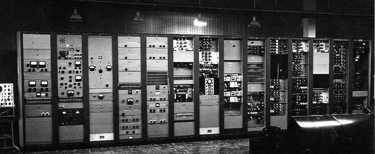
Terminal Equipment Racks
WCAU-TV
1954
(Click on the photo to see a larger version)
Here's some additional details on the RCA TT5-A transmitter. The TT5-A was a television broadcast transmitter with a nominal power output of five kilowatts peak aural power. It was designed to operate on any of the 12 VHF channels. The entire transmitter was housed in eight steel cabinets which were fastened to a base frame.
This frame was divided in such a manner that the eight cabinets could be placed in either a straight line with an overall width of 17 and a third feet (208") or in a "U-shaped" arrangement with the smallest possible width of 12 and a half feet (150"). Each cabinet was seven feet tall, with a depth of 38 inches and had both a front and rear door. The components and wiring, according to RCA, were arranged to permit maximum accessibility. The visual section of the transmitter was located on the right side and the aural section was on the left. The power supplies and control panel were for both sections were in the center.
The visual section of the transmitter consisted of a crystal oscillator followed by r-f amplifiers and a grid-modulated power amplifier. The use of the final amplifier, grid-modulation made possible the operation of all drivers stages as high-effciency, narrow-band, class "C" amplifiers, which could be tuned quickly and easily from front panel meter observations.
The final power stages of the aural and visual sections each used the RCA 8D21 dual tetrode operated as a push pull amplifier. Dual tetrode construction did away with the need for neutralization of these stages, assuring better picture quality and less likelihood of adjacent channel interference.
The aural section utilized the RCA Direct FM exciter, followed by amplifiers and the power amplifier. All high power circuits were protected by high speed overload relays backed up by thermal type circuit breaker switches.
Certain controls on the control panel such as "start-stop" and aural and visual input gain controls were duplicated on the console control supplied with the transmitter. In addition, the control console contained a picture monitor and oscilloscope, switches for operating tower lights, a VU meter for the aural channel, and meters which operated from the reflectometers in the transmission line. These meters gave indications for determining power output as well as standing wave ratio on the transmission line.
RCA said: In order to provide greater convenience in shipping and installation, the transmitter is partially disassembled which it leaves the factory. The largest unit, uncrated, is 25x30x80 inches, and no single unit weighs over 1000 pounds. This facilitates handling in confined spaces and elevators. All connections between units are made from conveniently located terminal boards on each unit.
The total weight of the transmitter unit was 8000 pounds. The console weighed 600 pounds and the water circulating system (it was water cooled) weighed 1300 pounds. Its finish was a two-tone umber gray with satin chrome trim and fittings. The RCA stock number was MI-19205-A plus MI-19205-B.
Broadcast Pioneers member Charlie Higgins explained how the RCA transmitters got their model number. TT was the transmitter type (TT=Television Transmitter). Next came the Output Power which in this case was 5 kilowatts. Finally, came the design. A stood for the first version. B, the second, etc. Thus, it was a TT5-A. For the transmitter installed in 1979 and 1980 (TT50-FH), it was TT for Television Transmitter. 50 for 50 kilowatts. F for the sixth version and H stood for High Band (channels 7 thru 13). L, by the way stood for Low Band or channels 2 thru 6.
![]()
From the official archives of the Broadcast Pioneers of Philadelphia
Photos originally donated by Charlie Higgins
© 2007 & 2011, Broadcast Pioneers of Philadelphia
All Rights Reserved

The e-mail address of the Broadcast Pioneers of Philadelphia is pioneers@broadcastpioneers.com